
Newsletter

|
Newsletter | |
| Number 10: March 2004 | ||||
| MERLIN | VLBI AT JBO | PROPOSALS | ARCHIVE | CONTACT |
This newsletter may also be downloaded as a pdf file from here
| Contents | |
Enhanced MERLIN Capabilities from First Stages of e-MERLIN Investment
The deadline for the receipt of proposals for Semester 04B (October 2004 - January 2005) on MERLIN is 15th March 2004. All details are in the MERLIN web area, specifically;
Observing frequencies available:-
The Lovell Telescope will be available at both L-Band and C-Band frequencies dependent upon the proposals received. Surface alignment of the Lovell telescope will be an iterative process with the second stage planned for Summer 2004. The new C-Band receivers and LOs are scheduled for installation during Semester 04A. Improvements and upgrades will be incremental and the fully enhanced sensitivity is unlikely to be realised before the latter part of 2004. Modified LO electronics together with new C-Band receivers should enable multi-baseline imaging of methanol and excited OH masers. New C-Band receivers should provide a ~25% improvement in sensitivity in the lower band. Overall improvement in sensitivity in the 4.5GHz-5.2GHz band by up to 2.5 resulting from new receivers and inclusion of the Lovell Telescope.
The system parameters for observation of a continuum source in good weather conditions are;
| C-Band(New) | C-Band | K-Band | |
| Maximum angular resolution (mas) | ~150 | ~40 | ~8 |
| R.M.S. noise level for 12 hr. on source (microJy/beam) | ~60/~30 | ~50/~20 | ~400 |
| Maximum bandwidth per polarization (MHz) | ~15 | ~15 | ~15 |
Proposal forms, information on MERLIN Key Programmes, and further general information can be obtained via;
The use of the fully aligned Lovell telescope at L-Band, and at C-Band with the new receiver systems reduces the 12 hour RMS noise level to ~30 microJy/beam and ~20 microJy/beam respectively. The maximum rate at which the observing frequency can be switched within an observing band will be approximately once every five minutes for multi-frequency synthesis (MFS) observations. MFS is possible within each C-Band range (e.g. 4.5GHz-5.2GHz), but not possible between 4.5/5.2GHz and 6/7GHz.
For spectral line work throughout the Semester, users are referred to Section 3.4 of the MERLIN User Guide Version 1.1. The maximum number of frequency channels per baseline to be divided between the 4 polarizations for bandwidths of 16MHz, 8MHz and 4MHz are 64, 128 and 256, respectively. The number of frequency channels per baseline to be divided between the 4 polarizations will be 512 for bandwidths of 2MHz or less. The minimum total bandwidth is 250kHz. There will be MERLIN+EVN observations at C-Band during October/November 2004. Applications to go to the EVN PC. Users who have obtained single-baseline (Mk2-Cambridge) data at 6-7GHz should inform the MERLIN TAG of the status of their project when applying for new observations with full MERLIN.
Spring is in the air and the thoughts of young men and women are supposed to turn in certain directions, you will be glad to know that ours are focused entirely on the National Facility! As I look back on my report for last September's Newsletter it is with some chagrin that I remember some advice that an NRAO colleague gave me many years ago; he said "Never tell them what you are going to do, always tell them what you have done!" Last year we had hopes of signing the e-MERLIN fibre-optic contract within a few weeks of the issuance of the Newsletter. I can now inform you (and ignore the above advice) that we will be signing the contract very shortly. The legal and contractual issues associated with this have been more complex than we thought and have thus taken longer to resolve. However, as Simon Garrington's report below indicates, that has not resulted in the rest of the project standing still; we have made significant progress in all other areas and the hardware is beginning to appear on the telescopes. Tom Muxlow's report on the first image made with MERLIN and the Lovell Telescope at 5 GHz is an excellent example of the new capabilities that are already appearing.
Our engineering staff has the ability to redefine the length of the seasons and so the 'summer' engineering period stretched until January. This was a result of major engineering on two telescopes: a) the first of the new L-Band lens mechanisms was installed on the Pickmere E-systems dish - this project is described below by John Kitching; and b) the Defford telescope was totally re-cabled. Both were major projects, complicated by the fact that daily travel to each telescope takes up a significant part of the working day. The inevitable consequence of this lengthy engineering period was that observing time was lost. In effect, we lost all of Semester 03B; however, users have been informed that all Priority A programmes will receive observing time in 2004.
A major success was the National Facility's involvement in the production of the first e-vlbi image ( see http://www.evlbi.org/evlbi/tevlb8/tevlb8.html). Our VLBI team, led by Paul Burgess, used the Cambridge 32-m antenna in cooperation with WSRT and Onsala on 15th January 2004. The data were transferred to JIVE, correlated and an image of the BL Lac 2007+777 was produced within 24 hours of the observation. This is hopefully the first of many such experiments which will lead to routine e-VLBI.
As reported in the previous Newsletter the National Facility is a key player in RadioNet, an EC-funded programme aimed at bringing together a broad range of institutes involved in operating and developing radio astronomy facilities. The project kicked-off on 1st January 2004. The most immediate impact visible to non-UK but European Union-based astronomers is that we can now cover the costs of such teams to use MERLIN. Any eligible team will be contacted by Tom Muxlow (Secretary of the MERLIN TAG) explaining how this can be of benefit to them. We will shortly be starting a campaign aimed at promoting MERLIN and the RadioNet programme across Europe.
P. J. Diamond (pdiamond@jb.man.ac.uk)
The C-Band receiver development is nearing completion: the new cryostat has been designed and is in production, further low-noise amplifiers are being built, a second orthomode transducer has been made and tested and a prototype superconducting hybrid coupler has been made and tested by the Emerging Device Technology group at the University of Birmingham. It is planned to have some of the completed systems installed ready for MERLIN + EVN observations at 6.7 GHz in May/June.
The first L-Band lens and its deployment mechanism have been installed at Pickmere (see article in this Newsletter). The lenses and mechanisms for the Knockin and Darnhall telescopes are being manufactured now and will be installed over the summer. The new L-Band horns, to be used with this lens, have been designed and will be manufactured in the next few months. A prototype InP low-noise amplifier at L-Band has been tested on the Cambridge telescope and has achieved a system temperature of ~30K.
Detailed designs of the analogue IF systems and the optical transmission systems have been completed and design reviews held. An 80-km optical link with multiple 10 Gb/s channels has been tested in the lab. Contracts for the optical fibre connections (trunk fibre and new digs) and the correlator are in the final stages of preparation and will be let in the next few weeks.
A proposal to build new X-Band (8.3 - 12.3 GHz) receivers for e-MERLIN has been submitted to the EC. This receiver band would provide new high-resolution and 12.2 GHz methanol imaging capability for e-MERLIN and would allow joint MERLIN+EVN observations at 8.4 GHz.
S. T. Garrington (stg@jb.man.ac.uk)
The first MERLIN image at 5GHz including the resurfaced Lovell telescope has recently been processed. Observations with the Lovell telescope at 5GHz for proposals approved from Semesters 03B and 04A are scheduled for May 2004. However, observations on Mkn273 with the Lovell telescope at 5GHz were taken in February in conjunction with a joint MERLIN/EVN program for PI Marco Bondi.
|
The first stage of panel alignment was carried out on the Lovell telescope during the latter half of 2003. Indications are that, following this first round of adjustments, the surface deformation is typically around 3 mm rms. Further rounds of adjustment are planned which should ultimately reduce this to the target of 2 mm rms or better.
Due to the complex nature of the program with calibrators, phase reference sources, and fringe finders, the resultant duty cycle gave a total integrated time on the target of only 5hrs 10mins. However, even with this relatively modest amount of time on source, the sensitivity improvement wrought by including the Lovell telescope is impressive. Without the Lovell telescope, MERLIN has typically achieved around 45-50 microJy/beam for a full imaging run approaching 12 hours on source. This latest map of Mkn273 has a noise level in the cleaned image of ~39microJy/beam. Early indications are that the inclusion of the Lovell telescope reduces the noise level by ~50% over a Mk2-only dataset.
|
Installation of new, more sensitive C-Band receivers are due to start during spring 2004, covering the bands 4.5 to 5.2GHz and the Methanol bands of 6 to 7GHz. After further rounds of surface adjustment to the Lovell telescope, the first of which is planned for Summer 2004, an overall improvement approaching 2.5 is expected, which should result in rms noise levels after 12 hours of integration ~20microJy/beam. These incremental upgrades are just part of the e-MERLIN project. A further major increase in sensitivity will come from the installation of optical-fibre links which increase the useable instantaneous bandwidth from 15MHz to 2GHz transforming the sensitivity by a factor of 12!!. When e-MERLIN comes on-line in 2008 we expect rms noise levels below 2microJy/beam in 5GHz images from full runs including the Lovell telescope.
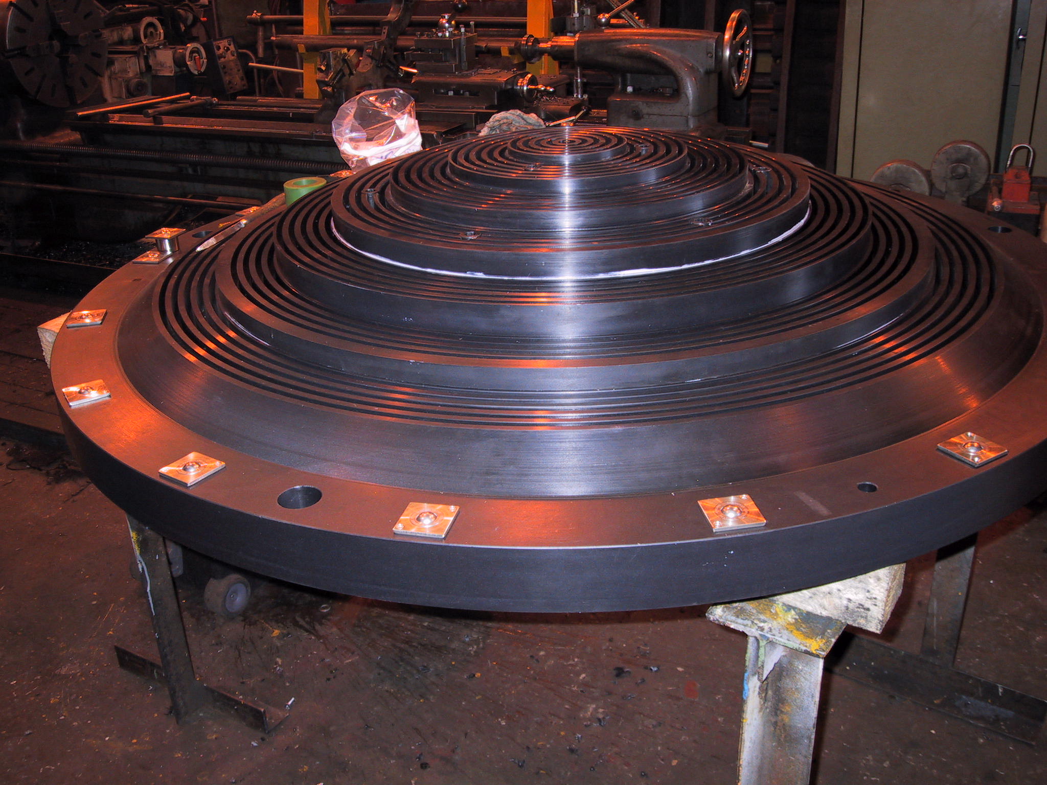
Part of the e-MERLIN upgrade of the E-Systems Telescopes, is to install a feed system consisting of a relatively small horn and a large lens, sited above the horn, which can be deployed separately when observations at L-Band are required. SHAL Engineers, Chesterfield, have recently carried out the manufacture of a suitable L-Band lens, together with a lens carrier mechanism. This frequency flexibility feature has recently been installed on the E-Systems telescope sited at Pickmere.
|
The lens is manufactured from high density polyethylene with a refractive index of approximately 1.54. Ideally, the lens would have been manufactured from a solid billet of material. Because of the relatively large dimensions of the lens (1.74m in diameter and 0.309m thick), a suitable solid billet of this material could not be sourced. Therefore, the lens had to be manufactured in three discs, which are bolted together. Particular attention has been given to the method by which the lens is clamped to the carrier framework. Calculations have shown that for a 30 degree temperature rise the lens may increase in diameter by 7-8mm and by 0.3mm in thickness. To allow for these changes in diameter, the clamping arrangement incorporates a series of stainless steel ball bearing units fixed both top and bottom into the periphery of the lens. The force exerted by each clamp is set directly through the centre of the ball bearing unit. The clamps are tightened to a preset torque, which allows a Belville washer to take up any changes in the thickness of the lens.
As the elevation of the telescope tends towards the horizon, and when the lens is deployed to the stowed position, the gravitational force of the Lens tends to act normal to the clamping force exerted through the ball bearing units. The mass of the lens is approximately 300kg. In order to contain the lens in these conditions, the clamping arrangement incorporates four `V` blocks, equi-spaced around the top of the carrier framework. These blocks are sited 45 degrees to the gravitational forces acting through the diameter of the lens. The ball bearing units at these points sit inside the `V` of the blocks which allows the lens to change in diameter, but also contains the lens during the critical conditions of its orientation.
|
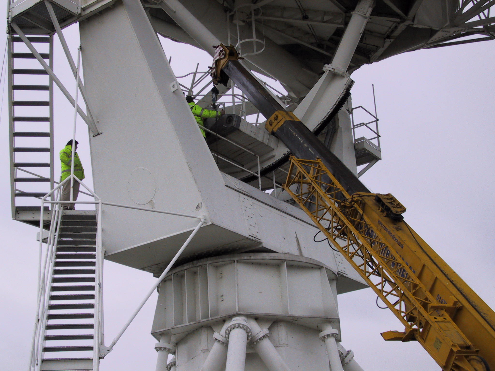
The lens carrier mechanism is a lightweight, yet stiff, aluminium fabrication, capable of sustaining the load generated by the lens at any angle of telescope elevation and any attitude of the lens deployment. In order to limit the RF interference, wherever possible, members used in the construction of the lens carrier sited above the horn, and in close proximity to the lens, have been formed using rounded cross sections. The carrier is fixed via a pivot bearing system to a pair of stiff fabricated steel plate supports. These supports are bolted to the steel structure within the vertex cabin, which have the greatest load bearing section modulus. The mass of the lens carrier assembly is approximately 1000kg. When not required for observations, the lens is stowed in the least populated volume within the vertex cabin. This position is coincidental to the elevation axis and is due to the offset of the carousel from the main optical axis of the telescope. For L-Band observations, the lens travels from the stowed position to the observe (zenith) position in less than 1 minute (and vice-versa). It is possible to deploy or stow the lens at any elevation angle of the telescope. In order to help maintain the true observation position of the lens, a mechanical stop/lock mechanism has been incorporated into the fabricated torque bar of the carrier mechanism. With the present feed configuration, the lens may be deployed when the carousel is at any angle of rotation. The lens is deployed through a motor/gearbox and lead screw jack assembly. At present, the observe and stow positions of the Lens are set by limit switches and the drive is operated manually via a hand held control box. A remote control facility will be incorporated into the L-Band frequency system later this year.
Following the installation of, a series of commissioning tests were carried out to verify the mechanical performance of the assembly. The observe position and the level of the lens were set using the existing 5GHz feed as a datum point. A laser pointer was fitted onto a stiff plate, which was secured to the input end of the feed. With the telescope at the zenith, the position of the laser spot was noted. The telescope was then driven from the zenith to the horizon in 10 degree intervals. At each interval the position of the spot on the lens was noted. This test was repeated from the horizon and back to the zenith. The results showed a maximum of 1mm deflection between the bottom of the lens and the input end of the existing 5GHz feed. An axial offset of +/- 5mm for this condition had been specified at the design stage. Further tests, again taken at 10 degree elevation stages, were carried out to examine the behaviour of the motor/lead screw drive, limit switch strikers, carrier pivot bearings and the mechanical stop/lock mechanism. During changes of the lens carrier positions from observe - stow - observe, all these aspects performed well within outlined specifications.
The mass of the lens and the lens carrier mechanism is approximately 1300 kg. In order to compensate for the downward turning moment applied to the telescope by fitting this amount of mass inside the vertex cabin, approximately 2100 kg of additional counterbalance weight had to be fitted to the existing counterbalance array. Stud mount points were fixed to the array in order to accommodate the extra mass required. During summer this year, similar L-Band installations will be carried out at both the Darnhall and Knockin E-Systems sites. A compact horn design to suit the E-Systems L-Band frequency system has been developed. This will be a corrugated tapered feed approximately 0.9m long, and 0.741m in diameter at the input aperture. The horn will be fabricated in three sand-cast aluminium sections, the sections being machined individually prior to fabrication. Installation of these L-Band horns should commence late summer this year.
John Kitching (gjk@jb.man.ac.uk)